Print #17 — The GoPro mount: engineering for motion
Title: Print #17 — The GoPro Mount: Engineering for Motion
A GoPro mount has to do something most 3D printed parts don't: survive motion.
Vibration from a bike. Shock from an impact. Constant micro-oscillation from engine vibration. Repeated adjustment to different angles. And it has to hold a €300+ camera while doing all of this.
This is where articulated assembly meets real-world mechanical stress.
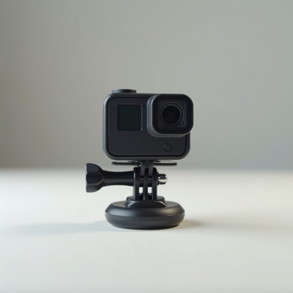
Understanding the GoPro mounting system: GoPro popularized a specific two-finger/three-finger fork mounting standard. Almost every action camera accessory uses it. The connection is two horizontal pins passing through aligned holes in two "fingers" that clamp a camera's mount plate.
Printing this precisely means:
- Hole diameter: typically 5.0mm (GoPro standard pin diameter: 4.8mm — needs 0.1–0.2mm clearance)
- Finger thickness: must match standard (usually 3.5mm per finger with 3.5mm gap)
- Material at the pin holes: must be thick enough to not crack when the thumb screw is tightened
Types of articulated joints in 3D printing:
Ball joints: A sphere sits inside a concave socket. Allows movement in any direction. The socket must be slightly smaller than the ball (0.3–0.5mm) to create enough friction to hold position.
- Print ball and socket separately
- Ball joints wear over time — PETG holds up better than PLA
Pivot joints (hinges): A rod through two brackets. Simple, strong, predictable range of motion. Works well for up/down tilt on camera mounts.
- Rod can be a printed pin, M3 screw, or a short piece of M3 threaded rod
- Print the hinge bracket with 4+ walls near the pin hole
Friction-lock joints: The GoPro fold-out arm style — a pivot with a thumb screw that locks it in position. The screw compresses the joint and friction holds the angle. This is the most reliable for vibration resistance.
Vibration resistance — why it matters and how to design for it: Vibration loosens connections over time. A mount that holds perfectly at rest may fail after 30 minutes on a motorbike. To counteract:
- Use friction locks (thumb screw) rather than snap or gravity locks
- Increase wall count to 5+ near pivot points
- Consider printing arm sections in PETG (more vibration dampening than PLA)
- Use thread-locking compound (Loctite) on screw connections
Printing for strength at pivot points: The weakest point of any articulated mount is where the arm meets the pivot. Here, print orientation matters enormously:
- Orient so layer lines run perpendicular to the bending stress at the pivot
- Add a generous fillet (rounded transition) in the design at stress concentration points
- If printing PLA, expect fatigue cracks at bends after heavy use — switch to PETG for longevity
Recommended settings:
- Layer height: 0.2mm
- Infill: 40–50% (much higher than decorative prints — this is a mechanical part)
- Walls: 5 perimeters at all pivot points and connection areas
- Top/bottom layers: 5
- Supports: required for overhanging fork geometry — use organic/tree supports for easier removal
- Speed: 35–40mm/s for articulated sections (precision over speed)
What can go wrong:
- Mount pivots freely but won't hold angle: thumb screw not tight enough, or ball/socket clearance too large — tighten the screw more, or reprint socket with 0.2mm less clearance
- Finger snaps when tightening thumb screw: walls too thin at pin hole area — reprint with 5 walls minimum, or use PETG
- Vibration works the mount loose over time: use thread-locking compound on pivot screws; consider a thicker arm design
The lesson beyond cameras: Articulated assemblies appear everywhere in maker projects: robotic arms, cable management arms, desk mounts, pan/tilt systems. The GoPro mount is a compact version of the same engineering challenge. Once you've printed and tuned one, you understand the language of all mechanical joints.
Ready to layer up? → Print #18: The Bike Clip: Engineering Parts That Must Not Fail